How to Build a Fuel Cell
Interested in building your very own DIY fuel cell? Horizon Educational is here to help. In the guide below we’ll take you through everything you need to know – from power requirements to materials to assembly – in creating an entire fuel cell using your own hands.
Step 1 – Determine how much power you need
One of the most important things you can do in building a DIY fuel cell is to determine the power requirements. Fuel cell stacks can be used to power anything from phones to laptops to cars, buses and even spacecraft. Any fuel cell can be designed to fulfill any power requirement by doing one thing: increasing or decreasing the size of the electrode area.
Under normal conditions the output voltage of a single cell is less than 1V (usually around 0.6 to 0.7 V). Expert fuel cell engineers are able to manufacture a system with over 0.8 V per cell if the optimal electronics, design, materials and operating conditions are selected.
If you’re thinking 0.8 V is quite a small current to power a lightbulb, computer or even space ship – you’d be right. This is why fuel cells are usually ‘stacked’ together in so-called fuel cell stacks. The number of cells stacked together is determined by the voltage the operator requires. Voltage requirements for common fuel cell applications can be seen below.
|
Application |
Maximum Voltage |
|
Cell Phone |
4.2 |
|
Laptop |
12.6 |
|
Automobile |
284 |
|
Stationary Power |
480 |
|
Centralized Power Generation |
100kV+ |
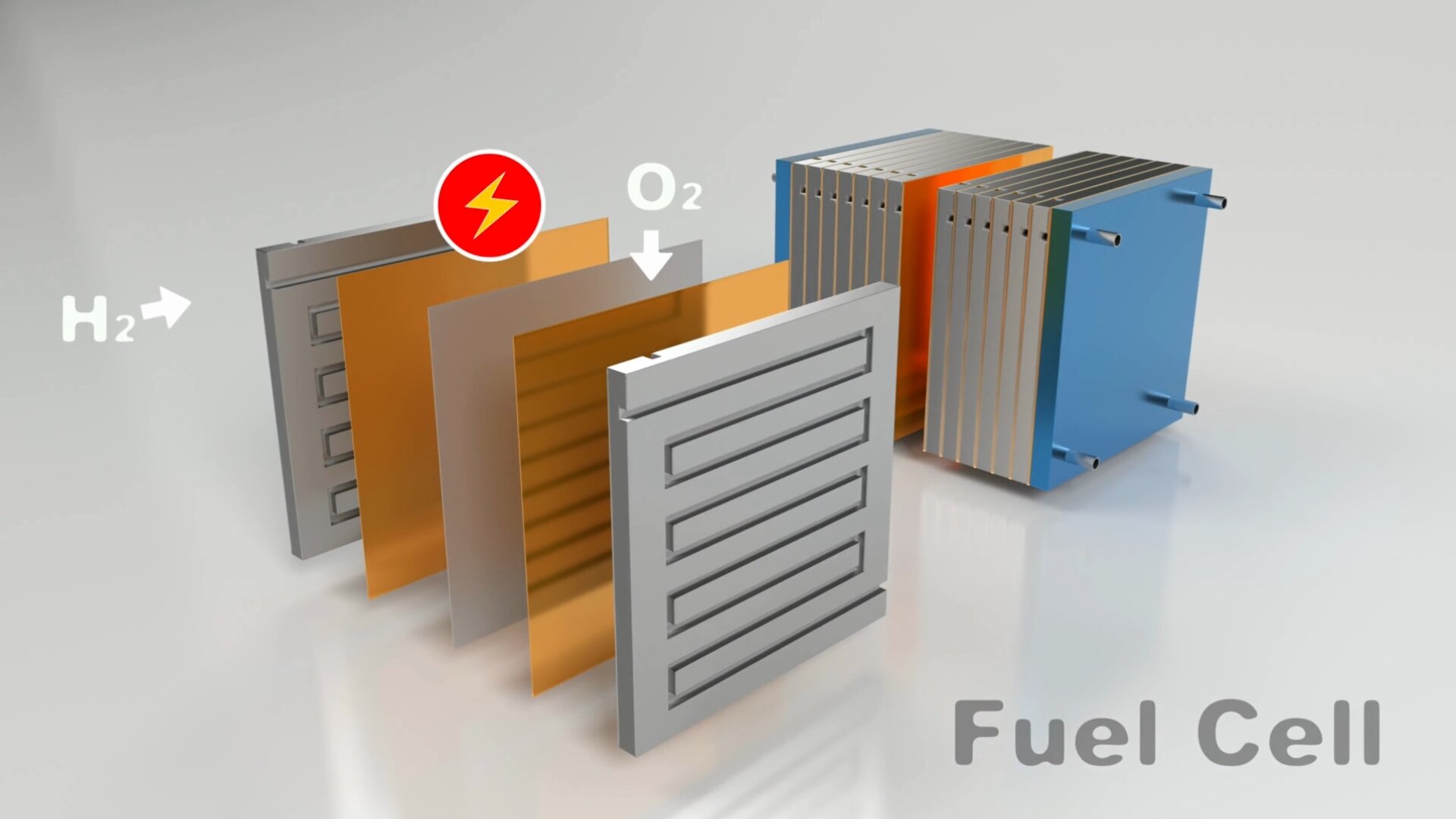
Step 2 – The different parts of a Fuel Cell
After you’ve determined the power requirements for the fuel cell, the next step is understanding the different parts of a fuel cell. Here’s a list of these different components:
- PEMs or ‘Proton Exchange Membranes’: These allow the flow of hydrogen atoms through the membrane while filtering out the hydrogen electrons.
- Catalyst: This breaks the fuel (usually hydrogen) into protons and electrons
- Catalyst Layers: On the anode side this includes particles of platinum that help split hydrogen molecules into protons and electrons, while on the cathode side, the platinum catalyst supports oxygen reduction, reacting with protons to produce water.
- Flowfield Plates: these regulate the flow of gasses and liquids (hydrogen, oxygen and water) through the fuel cell. This ensures a constant power output.
- Gaskets: these prevent fuel leakage, ensuring pressure remains equal throughout the stack.
- ‘Pickups’ or Current Collectors: These play a vital role in collecting electrons from the flow field plates.
- End Plates: These deliver critical support and help all components stay in place
- Claps, screws nuts and bolts: These are essential in holding the different components of the fuel cell stack together.
There’s also a variety of supplemental components that people add to fuel cell stacks to optimize performance. Humidification systems, digital monitoring systems and LED displays allow for real-time updates on efficiency and electrical characteristics of fuel cell stacks.
Step 3 – What materials do I need?
If you want to build a DIY fuel cell, you’ll need some basic materials. These include
- a proton-exchange membrane (such as Nafion),
- DI water solution, Hydrogen peroxide, and dilute sulfuric acid
- carbon fabric or paper
- a catalyst (usually platinum)
- graphite or another type of flow field plates
- gasket material (to seal the gases into the flow field area)
- metal to create current collectors
- end plates
- clamps, nuts or bolts to hold the fuel cell case together
- a hydrogen source
- a multimeter and oscilloscope as testing instruments
Step 4 – Consider the fuel cell operation
There are a few basic considerations that need to be taken into account when constructing your own fuel cell stack. It’s essential that fuel and oxidants are distributed evenly across the surface area of each cell. Without this, power and water generation will not be even and the electronics you operate will not function correctly.
Maintaining a consistent temperate throughout the fuel cell stack is crucial, but without quality components this can be difficult to achieve. It’s also important that the polymer electrolyte does not dry out or become oversaturated with water. Issues with water management can significantly decrease fuel cell performance. This is where the flowfield plates are critical – as they regulate the different liquids and gasses that flow through the fuel cell.
To minimize restrictive losses, it’s important you ensure good contact between conductive components so electrons can flow freely with minimum resistance. Additionally, the fuel cell stack itself must be tightly sealed to minimize gas leakage. This can be done with appropriately sized gaskets.

Step 5 – Prep the Polymer Electrolyte Membrane (PEM)
Nafion is the most commonly used polymer electrolyte membrane for low-temperature fuel cells. It comes in the form of a thin, clear film that needs cutting to fit your unique fuel cell design. How can you do prepare it once you’ve cut it to the perfect size? Dip it in a series of headed solutions containing DI water, hydrogen peroxide and dilute sulfuric acid to activate essential gas groups present in the membrane. These solutions are usually heated to around 80°C in glass beakers.
Why do we use the substances listed above?
- Distilled (DI) water is used to hydrate the membrane and clean it of all surface imperfections and pollutants.
- Hydrogen peroxide removes organic contaminants from the PEM surface
- Dilute sulfuric acid is essential in removing any metal ion from the membrane surface.
- Use DI water to rinse the sulfuric acid from the PEM membrane and hydrate it again
- Use DI water and rinse and repeat 2 more times to fully clean the membrane and ensure complete hydration.
To make sure your the film is hydrated evenly, ensure it remains completely submerged throughout the entire process. Remember to keep a close eye on the solution temperature, and maintain it at exactly 80°C. Once you’ve finished the process, allow the PEM to dry in a clean, well-ventilated environment.
Step 6 – Create the electrode layer
To create the electrode layer, a mix of platinum and powdered carbon are bonded to a gas diffusion layer – usually a carbon fibre cloth or paper that’s able to conduct electricity. The platinum breaks down the fuel (usually hydrogen) into protons and electrons. The protons move through the membrane and then recombine with oxygen to produce water. The electrons take a different path, through the catalyst to the gas diffusion layer, flow field plates and metal wires to create a flow of electricity.
Step 7 – Assemble the Membrane Electrode
Every membrane electrode assembly requires two separate sets of material for both the anode and cathode. A carbon fiber cloth (or other conductive paper) acts as a substrate, keeping the catalyst in place. It’s often coated with Polytetrafluoroethylene (PTFE) on one side to aid water management in the fuel cell stack. There are a variety of ways to assemble the catalyst layers in your first fuel cell stack (such as hand-painting, electroless deposition, or mechanical deposition), but print screening is usually the most cost-effective.
Use high temperature and pressure to fuse together the two electrode layers with the polymer electrolyte membrane (PEM). This fusion needs to be done well to ensure the proper flow of electrons and protons. The electrode layer is coated with liquid Nafion – you can apply this to one side of the catalyst that faces the polymer membrane (PEM). Do this with a consumer brush and dry it in a well-ventilated room at 20 C.
You’ll then need two heating plates heated up to 90 °C. Sandwich the three layers (electrode-PEM-electrode) in between these, and apply pressure for about one hour. This will allow all the solvents from the liquid nafion to evaporate. After one hour, raise the temperate of the plates to 130 °C over the next 30 minutes. Once the three layers reach 130 °C, apply even more pressure. After 2 minutes of intense pressure, turn the hot plates off and allow the three layers (now sandwiched together) to cool to room temperate. Now you’ll find that the electrodes and PEM membrane are fused together into a single unit. Well done!
Step 8 – Assemble the DIY Fuel Cell Stack
One of the most important things to do when assembling the fuel cell stack is making sure there are no cracks or gaps in the unit. If any fuel or air escapes, this would cause problems with the flow of air or hydrogen through the fuel cell. You’ll need some good-quality gaskets to accomplish this task. These need to be elastic enough to compensate for any irregularities in the surface of the flow field plates. They also need to be thick enough to endure compression. Great materials to use are rubber, silicon or polytetrafluoroethylene (PTFE). Place the gaskets around the flow field pattern to create a seal. This will prevent gas leakage.
To assemble: your three-layered electrode-PEM-electrode ‘sandwich’ should be mounted in the middle of a piece of polyester film (Mylar). This film will keep all gasses and compounds separate, ensuring they travel through the PEM membrane.
Now, collect all the components you need:
- 2x Endplates (these can be made of metal or some sort of polymer). Make sure they have the appropriate holes for clamping to the outer case of the stack.
- 2x Conductive end plates (these are also used as a current collector). Ensure it’s mounted to a non-conductive housing.
- 2 x Flow field plates (these ensure there are the right amounts of hydrogen and oxygen that flow to the PEM without losing pressure)
- PEM (three-layered electrode-PEM-electrode ‘sandwich’).
To assemble the fuel cell, add the following layers in a sequence:
- End Plate
- Conductive end plates (use gaskets to hold this in place)
- Flow field plate
- PEM (three-layered electrode-PEM-electrode ‘sandwich’).
- Flow field plate
- Conductive end plates (use gaskets to hold this in place)
- End Plate
If you’d like to increase the number of cells in your fuel cell stack – just add more layers of PEM and flow field plates. This will mean your fuel cell stack has more than one fuel cell in it, and you can increase or decrease the number of fuel cells in the stack depending on your own energy requirements. The most sophisticated stacks, like the ones used in trucks or spaceflight, usually have hundreds of cells stacked together to generate the required power output.
Step 9 – Test your fuel cell stack
Try to get hold of an oscilloscope and multimeter. These will give you readings for the power output and voltage. Once you’ve looked at the voltage and current, you’ll have ideas about how to change and improve your fuel cell stack. If you’d really like to have professional control and analysis of your fuel cell stack, you’ll need a professional test setup with different properties measured. Large-scale, industrial and commercial fuel cell stacks measure properties such as temperature, flow rates, pressure, humidity levels, and many other parameters.
Conclusion
Creating your very own DIY fuel cell stack is about having fun and learning about renewable energy. Following the steps above will allow you to learn about different science and engineering disciplines – such as electrical engineering, chemistry and physics – while seeing how these can be brought to life in a real-world application. As we’ve seen, important design aspects include power requirements, size, components, materials, and operating conditions. Try to experiment with these different parameters. After all, DIY is about having fun.

